Implementing a 4-bit counter using an 8051 and Interfacing it a
7-segment display
Introduction
In this lab, you will learn how to write a simple C program for
80X51 micro-controller, compile it using C51 compiler, and burn it
unto an 8051 chip. The program will be used to control a simple
4-bit up-down counter, capable of counting from 0 to F. At each step the
count should be displayed in hexadecimal on the 7-segment display.
You will control the the counter using a DIP switch which is also
interfaced to the 8051 chip.
For the seven segment display we will be using the LSD5061-11
chip. Each of the segments of the display is connected to a pin on the
8051 (the schematic shows how to do this). In order to light up a
segment on the the pin must be set to 0V. To turn a segment off
the corresponding pin must be set to 5V. This is simply done by
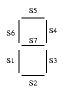
setting the pins on the 8051 to '1' or '0'. See the figure below
to determine which segment corresponds to which pin. This will be
important when you fill in you lookup table.
| Segment number |
LSD5061-11 Pin number |
8051 pin number |
| s1 |
pin 1 |
P2.0 |
| s2 |
pin 2 |
P2.1 |
| s3 |
pin 4 |
P2.2 |
| s4 |
pin 6 |
P2.3 |
| s5 |
pin 7 |
P2.4 |
| s6 |
pin 9 |
P2.5 |
| s7 |
pin 10 |
P2.6 |

Assignment
In this lab :
- You will design a 4-bit Up-Down counter using the
C programming language for the 8051 micro-controller
and display the count on an LCD.
- You will then burn your program on the 8051.
- The 4 bit counter has the following functionality:
- The counter has the following input pins :
- Reset : when high resets the counter
dataout to ``0000''
- Updown : decides whether the counter
counts up or down.
- Load : makes the counter count from the
4 bit input Datain
- Datain : which is a 4 bit input count
- The counter has a 4 bit Dataout to reflect the
count.
- The count has to be sent to the 7-segment display and
shown in hexadecimal format.
Apparatus Required
- 4.7k resistors(7)
- 330 resistors(2)
- DIP switch
- 7-segment display
- 5V power supply
- 8051 chip
- 12MHz crystal (clock)
Schematic

Program
#pragma SMALL DB
#include

/* P0, P1, P2 and P3 are predefined port names and are bit addressable */

sbit reset = P0^4; /* bit 4 of Port 0 */
sbit up_down = P0^5;
sbit load = P0^6;

void SetDisplay(unsigned char value){

    unsigned char LookupTable[17] = { 0xC0, .... };   /* fill in the */
                                                      /* rest of the lookup table */

    if( value >= 0 && value < 16 ) {
	/* assign port2 the appropriate */
	/* value in the lookup table */
    }
    else {
        /* assign port 2 the error */
        /* condition from the lookup table */
    }
}


/* Delay function */
void delay() {

    int i, j;

    for(i=0; i<1000; i++)
	for(j=0; j<100; j++)
	    i = i + 0;
}


void main(void){
    unsigned char count = 0;

    while(1) {
	if(reset == 1){
	    /* set count to 0 */
            /* display 0 on 7-seg */
	    delay();
	}
	else if(load == 1){
	    /* set count to the value read from port 0 */
	    /* display the value read on the 7-seg */
	    delay();
	}
	else{
	    if(up_down==1){
		/* increment count, keep it within bounds */
		/* display the value on the 7-seg */
		delay();
	    }
	    else{
		/* decrement count, keep it within bounds */
		/* display the value on the 7-seg */
		delay();
	    }
	}
    }
}
Procedure
Hardware
- Wire up the circuit as shown in the schematic.
- Pinouts are also available:
- 8051
- 7-segment display
Software
- Map your network drive to P:\\Peart\cs122
- Run the batch file cs122.bat
- Create a directory for your program on the C: drive (i.e. C:\Temp\counter)
- Using a text editor (i.e. notepad, etc...) type in the
program provided and add any necessary code to your program.
- Compile your program to generate object file count.obj
c51 count.c
- Link the object file to create your executable file count.omf.
bl51 count.obj to count.omf
- Create a hex file, count.hex, used to burn your
program unto the 8051 chip
oh51 count.omf
- Copy your hex file to a floppy
copy count.hex A:\count.hex
Burning A Chip - Programmer: MP-51
- Place the chip to be programmed on the slot making sure
that the correct side is up
- Use the arrow keys on the keyboard to choose options
- Choose Type -> 51Controller -> PC89C52U
- Choose File -> Load and enter the pathname of your hex file
(i.e. A:\counter.hex)
- Choose Command -> Program -> DeviceMemory -> Program Device Memory
- The chip will be programmed. Remove it from the chip from the
socket. It is now ready to be plugged into your board.
Testing Your Program
- Make sure that your chip has the power and ground
connections as specified by the schematic.
- Connect pin 9 to ground.
- Supply power to your board (make sure the power supply is
set to 5V, if it is higher you will damage the 8051
chip.)
- Pulse pin 9 to power then return it to ground.
- Your program should now be running. Test to see if it is
working correctly.
- If your program is not working as desired you will have to
modfiy your program, then compile and download unto the
chip again.

