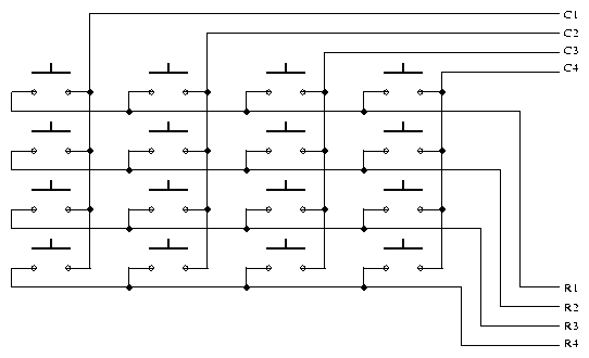
Fig 1. Keypad connection
Implementing a Calculator Using Peripherals Like a Keypad
Introduction
In this lab, you will build a simple calculator using the keypad as an input and the LCD as an output peripheral. After debugging and testing your program, you will have to burn the compiled program to a standalone 8051 chip at the end of this lab.
Keypads are often used as a primary input device for embedded microcontrollers. The keypads actually consist of a number of switches, connected in a row/column arrangement as shown in Fig 1.
In order for the microcontroller to scan the keypad, it outputs a nibble to force one (only one) of the columns low and then reads the rows to see if any buttons in that column have been pressed. The rows are pulled up by the internal weak pull-ups in the 8051 ports. Consequently, as long as no buttons are pressed, the microcontroller sees a logic high on each of the pins attached to the keypad rows. The nibble driven onto the columns always contains only a single 0. The only way the microcontroller can find a 0 on any row pin is for the keypad button to be pressed that connects the column set to 0 to a row. The controller knows which column is at a 0-level and which row reads 0, allowing it to determine which key is pressed. For the keypad, the pins from left to right are: R1, R2, R3, R4, C1, C2, C3, C4.

Fig 1. Keypad connection
Assignment
In this lab :
Apparatus Required:
Schematic:

Program:
/* To implement a integer calculator using a keypad and LCD */

#pragma SMALL DB OE
#include <reg51.h>
#include "io.h"

/* The functions to initialize and control the LCD are assumed to be in the file io.c */

/* Function to output the decimal value of the result on the LCD */
void PrintInt(int i) {
     .
     .
     .
}

/* Routine to scan the key pressed */
unsigned char key_scan()
{
       unsigned char i, j, temp1, temp2;

        while( 1 ) /* keep waiting for a key to be pressed */

                for(i=0; i<4; i++) {

                        /* Set each row to 0 */
                        P1 = 0xff & ~(1<<i);

                        /* Scan each column to see which key was pressed */
                        for (j=4; j<8; j++) {

                              /* Code to determine the position of the
                                 key which was pressed */
                              /* return(position) */
                        }
                }
}

void main() {

        /* You can have a conversion table to convert the key position into a
           valid number which indicates the operator or operand value. For eg:
           the numbers 0 to 9 are valid operands and 100 to 103 denote
           addition, subtraction, multiplication and division respectively */

        char conv_table[] = {

                 1, 2,  3, 100 /* add */,
                 4, 5,  6, 101 /* sub */,
                 7, 8,  9, 102 /* mul */,
                -1, 0, -1, 103 /* div */
        };
        char num1, num2, op;
        int result;

        InitIO();

        while(1) {

                ClearScreen();

                /* read num1 */
                GotoXY(0, 0);
                PrintString("num1 : ");
                do {

                    num1 = conv_table[key_scan()];
                }
                while( num1 < 0 || num1 > 9 );

                /* read a valid operation */
                GotoXY(0, 0);
                PrintString("op :   ");
                do {

                    op = conv_table[key_scan()];
                }
                while( op < 100 );

                /* read num2 */
                GotoXY(0, 0);
                PrintString("num2 : ");
                do {

                    num2 = conv_table[key_scan()];
                }
                while( num2 < 0 || num2 > 9 );

                /* compute result */
                if( op == 100 ) {

                     /* Add numbers and display result on the LCD */
                }
                else if( op == 101 ) {
                      .
                      .
                      .
                      .
                /* Continue similarly for other operations */

                }
        }
}
Procedure:
Note: Port 0 should not be used for output
because it does cannot sufficiently drive the LCD.
oh51 calc.out
Programmer: MP-51
A:\calc.hex