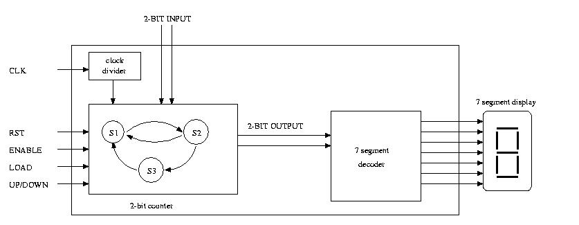
2-Bit Counter
I. Introduction

For this lab, you are required to write a vhdl description of a
finite state machine (FSM) and a testbench to show its correctness.
Inputs into your machine will be the following:
- clk: This signal will be used as a clock signal
- rst: This signal will be used to reset your machine when it
goes to '1' (active high).
- input: A 2-bit number that will be used to load a value
into the counter.
- up/down: This indicates if the counter will be counting
up or counting down. If this signal is high, the counter should
count down. If the signal is low, the counter should count
up.
- load: A one bit signal that indicates when you should
load a value into the counter from the inputs. When this value
goes high, you will load the value on Input into the counter.
- enable: If this signal is high, then the counter should
count. If this signal is low, the counter should stop.
II. Procedure
implementation and simulation
- Come up with the FSM that will describe how this
design should function.
- Translate the FSM into a VHDL description
- Test your design by writing a VHDL testbench and observing the
results in ALDEC Active-VHDL.
Downloading
- Once you have verified the results using Aldec VHDL,
check out an XS40 board to download your code.
- The clock on the XS40 is too fast to verify your counter.
You will need to add a clock divider
( clkdiv.vhd) to your code. This
will slow down the clock from your XS40 board to your
counter so that you can observe the results. The
output from the clock divider will only pulse once every
second. The schematic below will give you an idea
of how to connect the clock divider.
- Create a .ucf file for your design.
- Generate a bit file using Xilinx and download it
unto your XS40 board.
- Verify your results.


