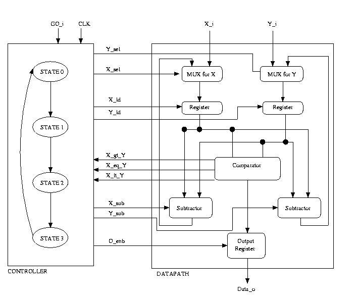
Sample Structure of the Controller and Datapath
FSM + D: Greatest Common Divisior
I. Introduction
The purpose of this lab is to implement a finite state machine in VHDL to calculate the Greatest Common Divisor(GCD) of 2 numbers.
The algorithim used to compute the GCD is as follows. Two numbers
are compared ( x = y ?). If so the the GCD is found. If x > y,
then x = x - y. The two numbers are then compared once again. If y >
x, then y = y - x. The two numbers are then compared once again. Here
is and example of our algorithim:
x = 10
y = 2
Is x = y? No, x > y therefore x = x - y
in our case, x = 10 - 2 = 8.
Is x = y? No, x > y therefore x = x - y
In our case, x = 8 - 2 = 6.
Is x = y? No, x > y there fore x = x - y
In our case, x = 6 - 2 = 4.
Is x = y? No, x > y therefore x = x - y
In our case, x = 4 - 2 = 2.
Is x = y? Yes, therefore the GCD of 10 and 2 is 2.
Note that 0 is not a valid input.
The design of the GCD calculator should be divided into 2 parts - a controller and a datapath. The controller is an FSM which issues commands to the datapath based on the current state and the external inputs. This can be a behavioral description. The datapath contains a netlist of functional units like multiplexors, registers, subtractors and a comparator, and hence this design is structural. The controller basically steps through the GCD algorithim shown above. If x = y, we have finished computing the GCD, and we go to the final state and assert the data output line. The Datapath does the actual GCD computation. It has the following components:
II. Procedure
implementation and simulation: