Reflex Timer


I. Introduction

Microcontrollers often need to perform operations based upon some length of time. This can be used for communication purposes (e.g., serial communication), event counters, measuring time, or performing operations at certain intervals.

The 80c51 has 2 16-bit timer/counters registers which can be configured to perform a variety of operations. When configured as a timer, the timer will count from the user specified value down to 0. Upon reaching 0 an interrupt will be generated, at which time an interrupt service routine can be performed. The following timer register descriptions provide the neccessary information for the timers/counters in the various modes of operations.

Timer Register Descriptions:


       TMOD Timer Mode Register

       ------------------------------
      |Gate|C/T|M1|M0|Gate|C/T\|M1|M0|
       ------------------------------
      |<-Timer 1----><---Timer 0 --->

      Gate Gating Control.
           0= Timer enabled
           1 = Timer enabled if INTx\ is high

      C/T\ Counter or Timer Selector
           0 = Internal count source (clock/12)
           1 = External count source (Tx pin)

      M1, M0 Mode Control
          M1 M0          Mode
          ----------------------------------
          0   0    Mode 0, 13 bit count mode
          0   1    Mode 1, 16 bit count mode
          1   0    Mode 2, Auto reload mode
          1   1    Mode 3, Multiple mode

-----------------------------------------------------------------------------

        TCON Timer Control Receiver Register

        ---------------------------
       |TF1|TR1|TF0|TR0|  |  |  |  |
        ---------------------------
       <-Timer Controls><-Unused for timers

        TRx Timer x run control
            0 = Timer not running
            1 = Timer running

        TFx Timer x flag
            0 = timer has not rolled over
            1 = timer has rolled over

----------------------------------------------------------------------------

     Formula to load the value of TH1 corresponding to required baud rate

          Clock Frequency (12 MHz)
          -----------------------  = Baud Rate
          12 x 32 x (256-TH1)


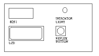
In this lab you will build a reflex timer to measure a person's reaction time. The reflex timer works by lighting up an led after a random lenght of time and the user will have to respond by pushing a button as quickly as possible. In this lab you will need to calculate how long it took the user to respond and display it on the LCD in milliseconds (10-3 seconds).

The specs are as follows:

  1. On initial power up the LCD should display "Reflex Timer"
  2. The user will then press the button to start
  3. At a random time the indicator light will illuminate

II. Schematic:

The materials needed are listed and a general setup is provided. However, it is your job to figure out the connections.
HINT: you can refer to previous labs, we have used all these components previously.

III. Apparatus Required:

  1. button (1)
  2. led (1)
  3. LCD
  4. 8051
  5. 5V power supply
  6. Philips PDS51 development board

IV. Program

/* main.c */

#pragma SMALL DB OE
#include 
#include 
#include "io.h"

/*----------------------------------------------------------------------*/
/* define the DEFAULT value here */
unsigned short TIMER_COUNT = DEFAULT;		/* see default */

/*----------------------------------------------------------------------*/

sbit slight; /* assign to ports */
sbit button;

/*----------------------------------------------------------------------*/

/* define your variable here */

/*----------------------------------------------------------------------*/

static void StartTimer(void) {

}

/*----------------------------------------------------------------------*/

static void InitTimer(void) {
	EA = 0;
	TR0 = 0;
	TMOD &= ~0x0f;
	TMOD |= 0x01;
	TL0 = (TIMER_COUNT & 0x00ff);
	TH0 = (TIMER_COUNT >> 8);
	PT0 = 0;
	ET0 = 1;
	TR0 = 1;
	EA = 1;
}

/*----------------------------------------------------------------------*/

static void StopTimer(void) {

}

/*----------------------------------------------------------------------*/

static void Timer(void) interrupt 1 using 2 {	/* reload */   

}

/*----------------------------------------------------------------------*/

void delay()  {
	int i, j;

	for(i=0; i<1000; i++)
		for(j=0; j<50; j++)
			i = i+0;
}

/*----------------------------------------------------------------------*/

void main(void){

   int number, cheating;
	
   InitIO();
   InitTimer();

   ClearScreen();
   PrintString("Reflex T");
   GotoXY(1,0);
   PrintString("imer");

   while(1){  

      while(button==1);
      cheating=0;			/* initialize stuff */
      ClearScreen();
      PrintString("Wait for");
      GotoXY(1,0);
      PrintString(" light");
      delay();
        
      /* get random number to turn light on*/	

      /* check if user pushed button before indicator
         light illuminated */

      /* did the user run out of time? */

      /* if not cheating and not out of time, 
         turn reflex light off and show results*/	

   }
}

V. Procedure:

  1. Figure out the connection need for your circuit and wire it up.
  2. Finish the program and test for correctness using the emulator. You will also need io.c and io.h.
  3. Burn an 8051 chip, and demo your lab for the TA.