FSM: VHDL Calculator
I. Introduction
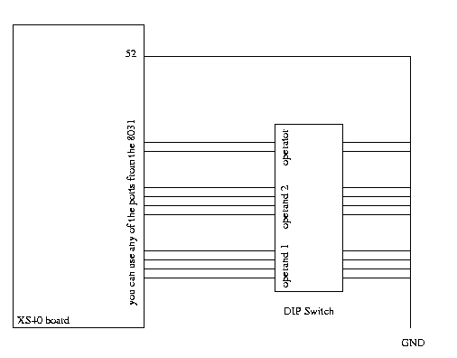
The purpose of this lab is to implement a finite state machine in VHDL to perform three simple calculations: addition, subtraction, and multiplication. You are required to design a calculator using VHDL. It should take in 3 inputs: two 4-bit operands and a 2-bit operator. Check it's functionality using ALDEC VHDL simulator, then wire up the DIP switch to the XS40 board and download your program unto XS40 board and verify correctness again.
Apparatus Required:
Schematic:
Program:
--
-- Tony Givargis
--

--********************************************************************

library IEEE;
use IEEE.STD_LOGIC_1164.all;
use IEEE.STD_LOGIC_ARITH.all;

--********************************************************************

entity WRLED is
   port (rst: in STD_LOGIC;
         clk: in STD_LOGIC;
	 val : in UNSIGNED(3 downto 0);
         led: out UNSIGNED(6 downto 0));
end WRLED;

--********************************************************************

architecture WRLED_arch of WRLED is

-- finish entity

end WRLED_arch;

--********************************************************************

library IEEE;
use IEEE.STD_LOGIC_1164.all;
use IEEE.STD_LOGIC_ARITH.all;

--********************************************************************

entity XS40 is
   port (rst: in STD_LOGIC;
         clk: in STD_LOGIC;

         --define operands and operator here

         led: out UNSIGNED(6 downto 0));
end XS40;

--********************************************************************

architecture XS40_ARCH of XS40 is

   component WRLED
      port(val: in UNSIGNED(3 downto 0);
           led: out UNSIGNED(6 downto 0));
   end component;

   signal val:UNSIGNED(3 downto 0);

begin

   U1:WRLED port map(val, led);

   process(rst, clk, ...)

   -- insert calculator code here

   end process;
end XS40_ARCH;
I. Procedure
simulation:
downloading:
(Remember: Jumper on J4 needs to be set when loading program
but disconnected when running program)